Breakout Board for microSD Card
MicroSD memory cards (originally known as TransFlash) provide a compact and inexpensive way to add gigabytes of non-volatile storage to a project. All SD cards support communication over the SPI (Serial Peripheral Interface) bus, making it straightforward to interface one of these cards with an SPI-capable microcontroller.
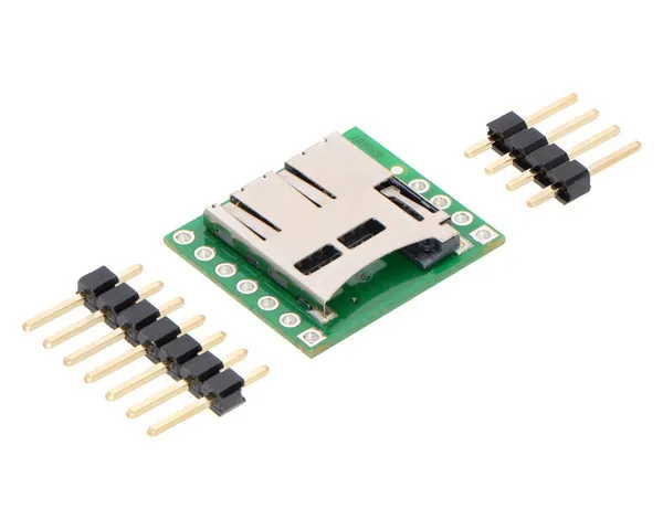
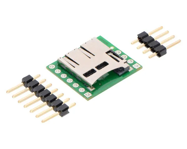
This carrier board makes it easy to connect to a microSD card by breaking out all of the contacts from a microSD card socket into two rows of 0.1″-spaced pins. The board measures only 0.8″ × 0.7″, and a set of breakaway 0.1″ male header strips (one 1×7 and one 1×4) is included, which can be soldered in to use the board with breadboards, perfboards, or 0.1″ female connectors. (The headers might ship as a single 1×11 piece that can be broken in two).
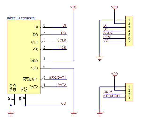
The following tables describe the function of each pin on the breakout board in SPI and SD mode:
| Pin | Description | ||
|---|---|---|---|
| GND (VSS) |
Power and logic ground | ||
| VDD | Supply voltage (2.7 V to 3.6 V for standard microSD cards) | ||
| CD | Card detect. When a card is inserted, this pin is floating; when no card is inserted, it is shorted to ground. A pull-up resistor can be used to pull the line high when a card is present. | ||
| SPI mode | SD mode | ||
| Pin | Description | Pin | Description |
| DI | Data in (MOSI) | CMD | Command/response |
| DO | Data out (MISO) | DAT0 | Data (bit 0) |
| SCLK | Clock | CLK | Clock |
| CS | Chip select (active low) | DAT3 | Data (bit 3) |
| — IRQ |
Reserved Interrupt (active low; SDIO devices only) |
DAT1 IRQ |
Data (bit 1) Interrupt (active low; SDIO devices only) |
| — | Reserved | DAT2 | Data (bit 2) |


Breakout Board for microSD Card
MicroSD memory cards (originally known as TransFlash) provide a compact and inexpensive way to add gigabytes of non-volatile storage to a project. All SD cards support communication over the SPI (Serial Peripheral Interface) bus, making it straightforward to interface one of these cards with an SPI-capable microcontroller.
This carrier board makes it easy to connect to a microSD card by breaking out all of the contacts from a microSD card socket into two rows of 0.1″-spaced pins. The board measures only 0.8″ × 0.7″, and a set of breakaway 0.1″ male header strips (one 1×7 and one 1×4) is included, which can be soldered in to use the board with breadboards, perfboards, or 0.1″ female connectors. (The headers might ship as a single 1×11 piece that can be broken in two).
The following tables describe the function of each pin on the breakout board in SPI and SD mode:
| Pin | Description | ||
|---|---|---|---|
| GND (VSS) |
Power and logic ground | ||
| VDD | Supply voltage (2.7 V to 3.6 V for standard microSD cards) | ||
| CD | Card detect. When a card is inserted, this pin is floating; when no card is inserted, it is shorted to ground. A pull-up resistor can be used to pull the line high when a card is present. | ||
| SPI mode | SD mode | ||
| Pin | Description | Pin | Description |
| DI | Data in (MOSI) | CMD | Command/response |
| DO | Data out (MISO) | DAT0 | Data (bit 0) |
| SCLK | Clock | CLK | Clock |
| CS | Chip select (active low) | DAT3 | Data (bit 3) |
| — IRQ |
Reserved Interrupt (active low; SDIO devices only) |
DAT1 IRQ |
Data (bit 1) Interrupt (active low; SDIO devices only) |
| — | Reserved | DAT2 | Data (bit 2) |